Hello Joe, I apologize for my mistake but I was not able to copy the images in-line with the text. Here is my original post with images placed appropriately:" Hello Joe,The ability to "synchronize"
your on board sample clock to an external clock will depend on the
frequency of the external clock. I have copied the block diagram for
the clocking circuitry on the NI 6551 below. This diagram is in the
section entitled "Clocking" in the NI 655x section of the <a href="http://digital.ni.com/manuals.nsf/websearch/28328731D00E483786257361005589B4" target="_blank">NI Digital Waveform Generator/Analyzer Help</a>.
As you can see, there is no clock divider circuitry on the NI 6551 that
directly divide down an external clock, only the clock divider for the
internal clock highlighted in the figure. <img src="
Loading Image...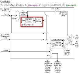
"> However,
rather than dividing down the external clock on board, you can PLL the
on board clock to a 10 MHz Reference Clock and that will ensure that
your sample clock is phase synchronized to your external clock.
However, as shown on page 17 of the <a href="http://www.ni.com/pdf/manuals/373309d.pdf" target="_blank">NI PXI/PCI-6551/6552 Specifications</a>, the external reference clock must be almost exactly 10 MHz (I have copied this information for your reference below. <img src="
Loading Image...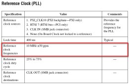
"> Another
important factor about the reference clock is that it is limited to
terminals that can accept a higher bandwidth (10 MHz) signal. Again,
this issue is addressed in the NI Digital Waveform Generator/Analyzer
Help in the section "Clock Sources Summary" under the NI 655x section, which I have copied below.<img src="
Loading Image...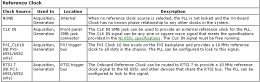
"> I hope this information addresses your question, feel free to post back if you have any other questions.
"


